
This is part two of my electrical system, for part one go here. In this I’m going to talk in more detail about the individual components, why they were chosen, and how they were made if I had to make them. Once again this is for entertainment purposes only and is not intended to be instructional in anyway. If you attempt any of this and blow your shit up I’m not responsible.
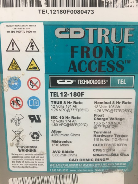
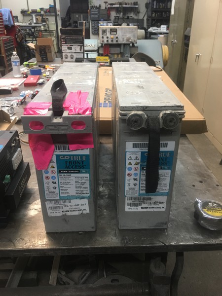
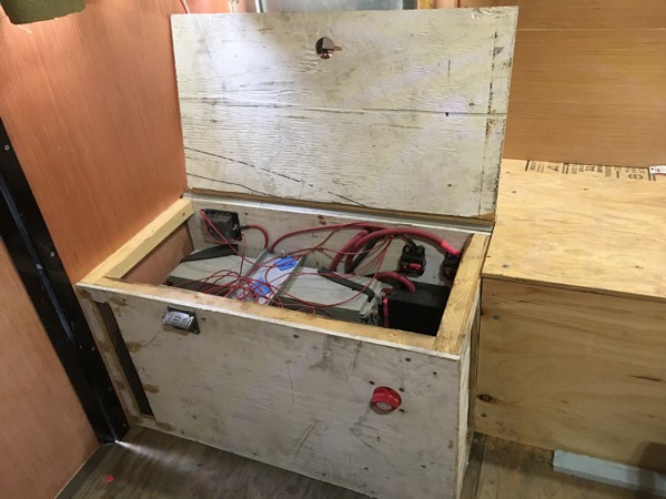
For batteries I went with two 180 ah, AGM (Absorbent Glass Mat) deep cycle batters. These particular batteries are marketed for the telecom industry but they work well in these set ups. AGM has a relatively long life and is maintenance free making it a good choice for my system. AMG Batteries can also go long periods of time without being charged so if I park the camper for a while I can shut down my system without worrying about the batteries going bad.
I really liked the dimensions on these, they are tall, skinny, and long so they fit perfectly side by side in the space I had available for them. I got a smoking deal, they weigh about 90lbs each, you really shouldn’t stack one battery on top of another and someone set a full pallet of batteries on top of another crushing the bottom pallet. Not all of them were completely destroyed but they were unsellable so I got two of them for scrap rate, pennies on the dollar.
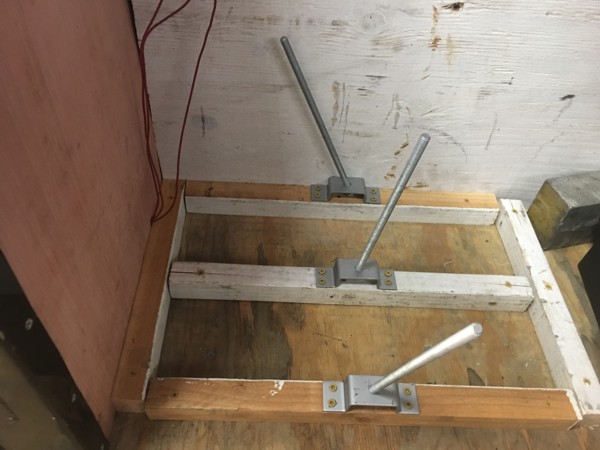
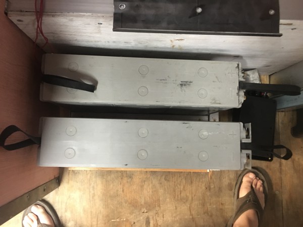
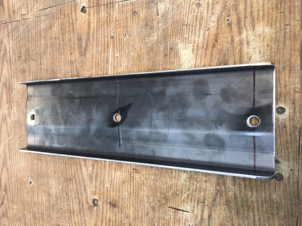
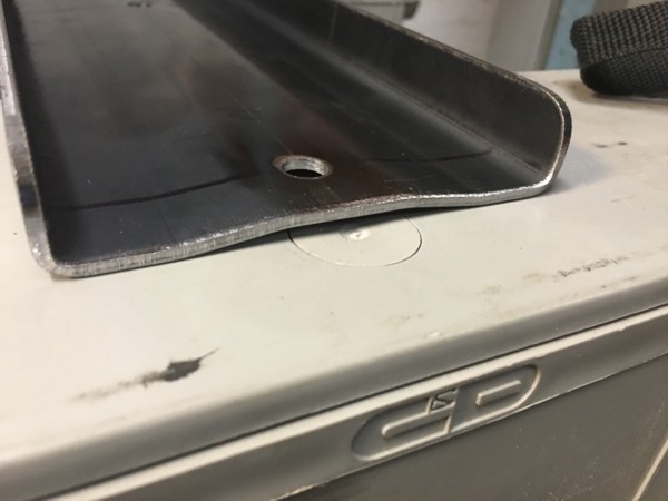
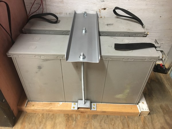
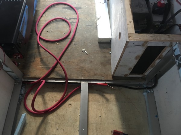
To mount the batteries I built a 2X2 wood frame that captured the bottom of the two and screwed it down to the floor. I custom made brackets with all tread sticking up that were long enough to reach the top of the batteries. There are circular vents on top of the batteries that cannot be covered so I made a custom hold down that was broke up out of sheet metal to allowed ventilation. This then gets tightened down onto the all thread with three nuts. I made the frame at the bottom such that the batteries would have a gap and not touch each other or the walls to help keep them cooler.
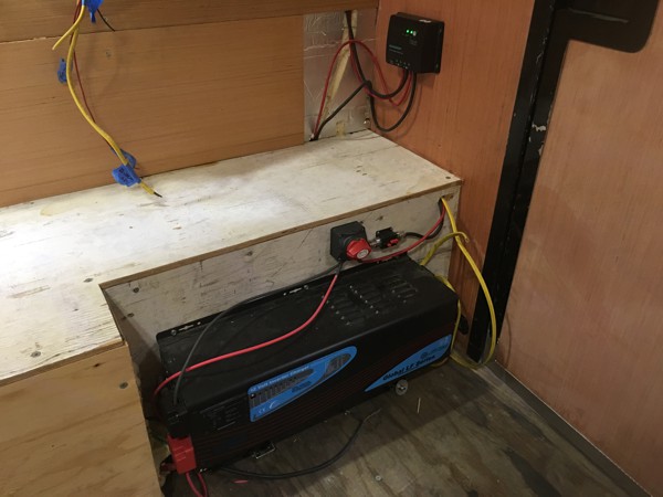
From here I built a box around the batteries with vents on two side to allow the box to breath. I covered the vent with perforated metal to keep unwanted objects out of the box. If I start to have over heating issues I can put a fan in but for now I’m going without.
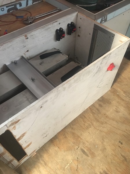
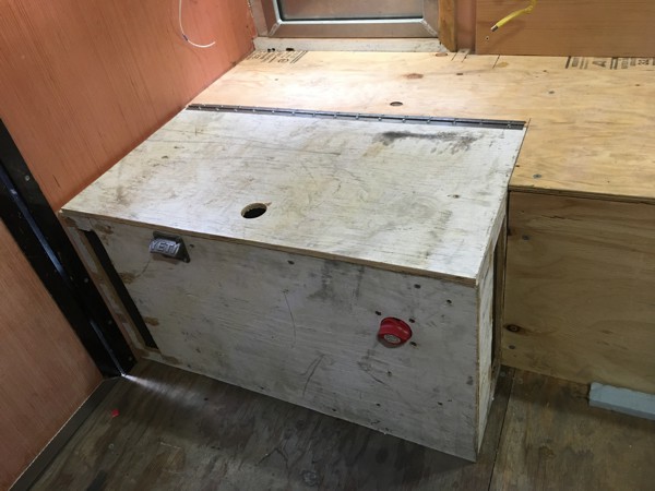
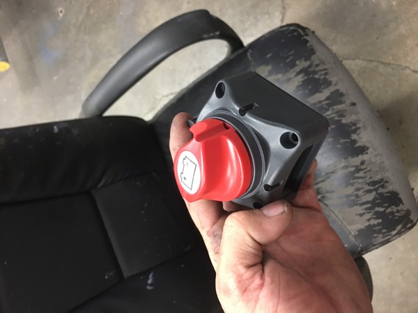
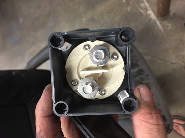
The red dial you see on the front of the box is the kill switch for the batteries. Flipping the clunker will kill all power to the system except for the power coming from the solar panels but I have a clunker on them as well.
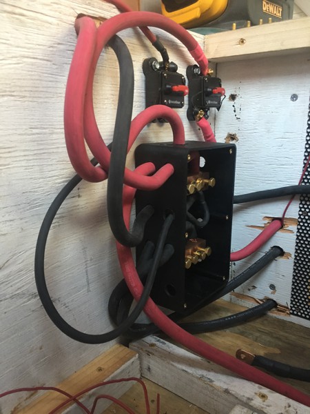
The power from the solar panels comes into a charge controller and then into a clunker and a breaker then on to the front end of the inverter. I tied in here as a short cut to the batteries instead of running another set of wires under the floor.
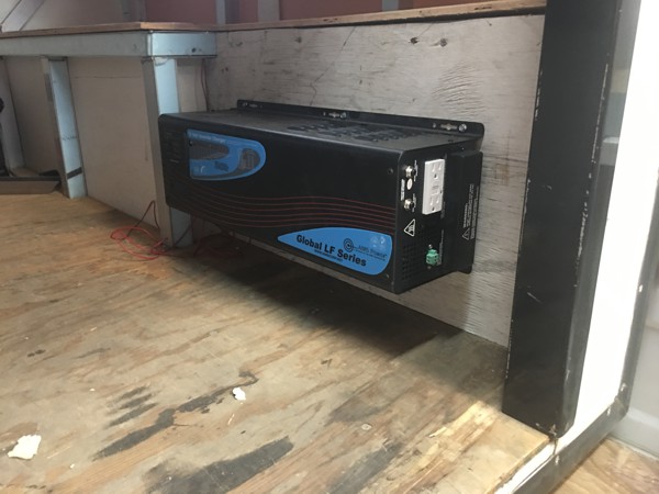
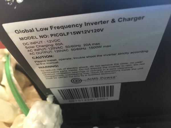
I went with a 1500W inverter from Aims, the highest draw I will have is my coffee maker at 900W so there was no need to get any bigger. This is a pure sign inverter which is a cleaner inversion and will run certain things like my variable speed sewing machine better. It also has the ability to plug into an extension cord and charge the batteries when I have shore power available. Efficiency is everything when it comes to inverters. You lose power when inverting from DC to AC but this inverter runs at 88% efficiency so I won’t lose as much. The biggest drawback is the noise. It has a fan on it that isn’t really that loud but in the confines of a camper it seems louder. I’m just going to turn it off when I’m not using it and deal with it when I am.
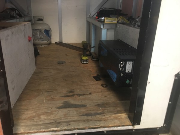
I didn’t have room for the inverter in the battery box so I had to put it on the other side under the fridge. Not a big deal but it meant I had to use a bigger wire. At its peak the inverter will draw 275 amps so I put a 300 amp breaker on it which meant 0awg wire at the distance I was running.
Of course all of the wiring is run under the floor.
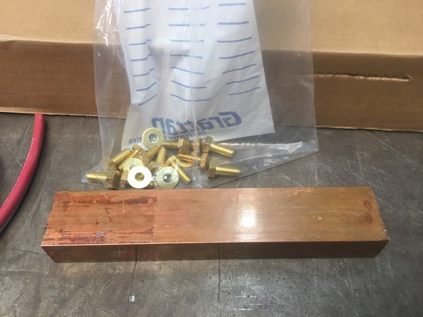
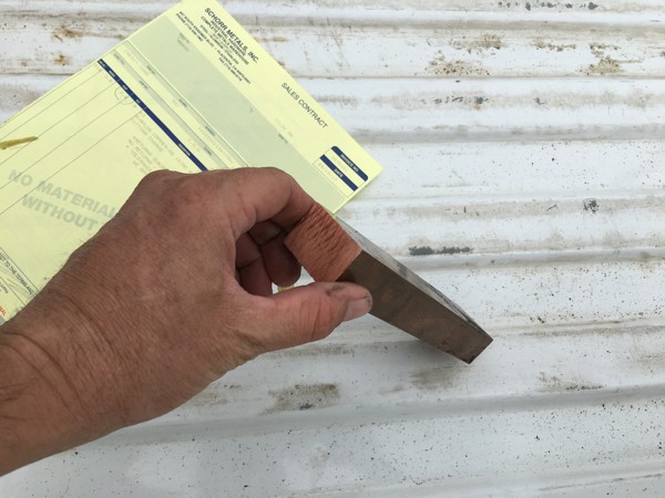
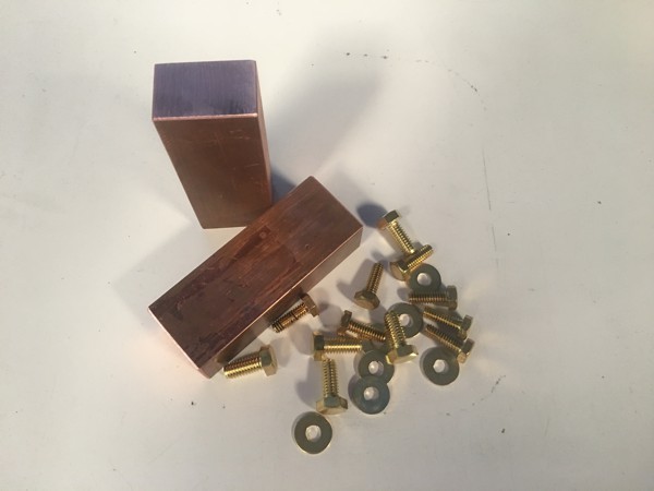
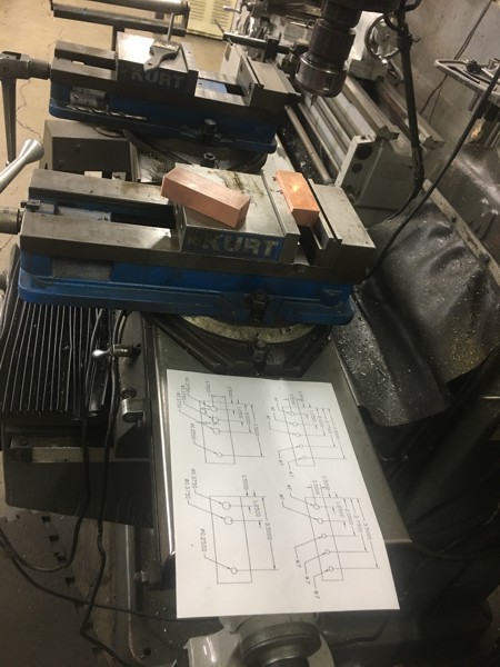
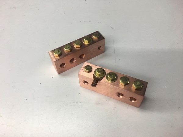
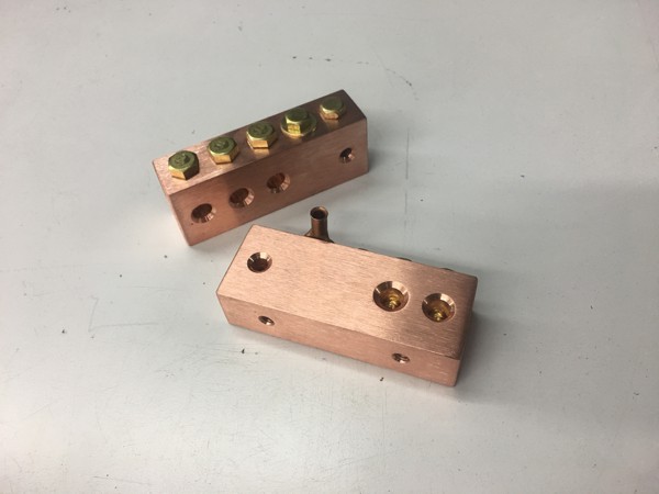
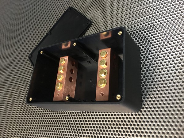
I needed a busbar that could handle 500amps and had trouble finding one so I decided to make one. I found a calculator online somewhere that said I needed something like 3/8”X3/4” copper bar but when I got to the shop I found a chunk of 1”X1 ½” copper bar and I got it at scrap rate, alittle overkill but I figured what the hell. I cut it in half and machined the holes I needed for all my different wires. I used brass bolts and washers for conductivity.
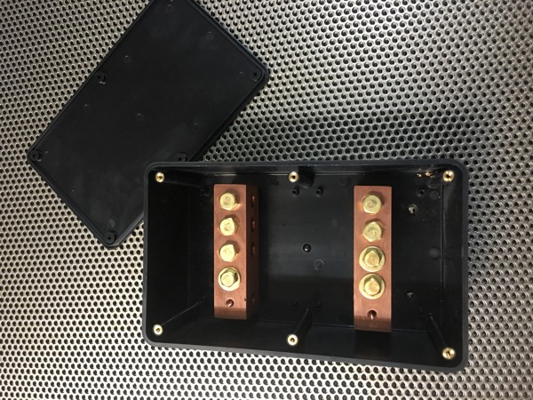
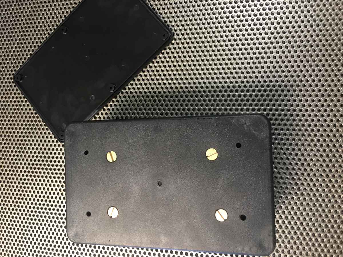
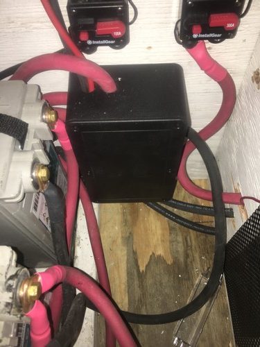
To protect the busbars I bought an ABS plastic box with a screw on lid from Amazon and mounted the bus inside, positive on top and negative on the bottom. I drilled holes in the sides of the box and ran all of my wires, I wanted to put strain reliefs on each wire but the box I got was too small and didn’t allow for it. I don’t think this will ever be a problem though so I’m not going to worry about it.
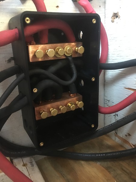
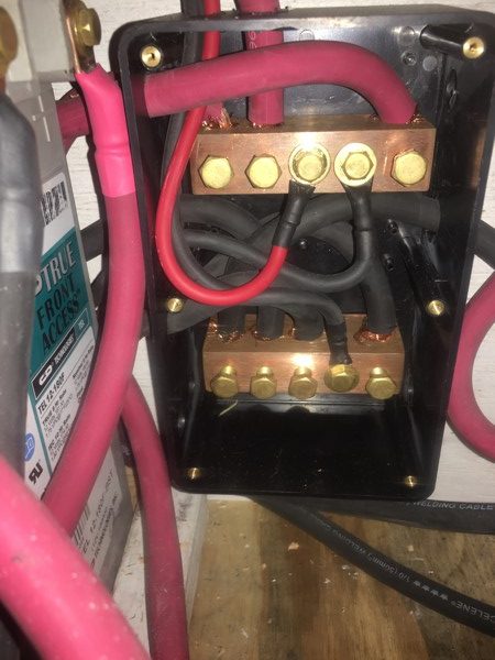
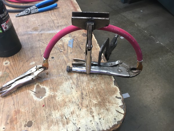
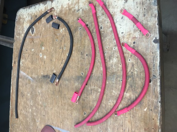
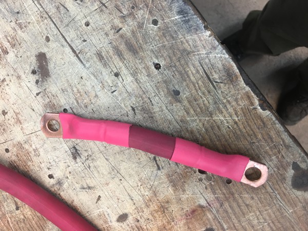
I used solder connectors for all my wire ends. I didn’t have a wire vise so I had to get creative. I used red wire for positive and black for negative to keep it all straight. I made sure to heat shrink the ends so noting would be exposed. I did use a black wire on the positive side in one place because the supply house was out of 8awg in red the day I went to get it. I shouldn’t let it bother me but it does and I will likely replace it later when I have a chance. The wire is only 24” long so it won’t be expensive. It runs from the buss to the breaker that runs to the fuse box for my DC power.
0 Comments