
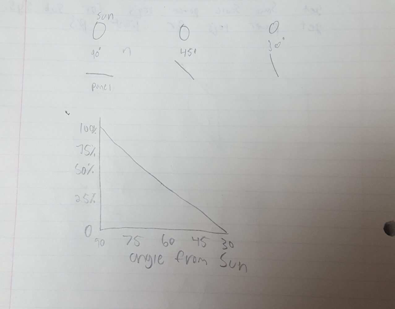
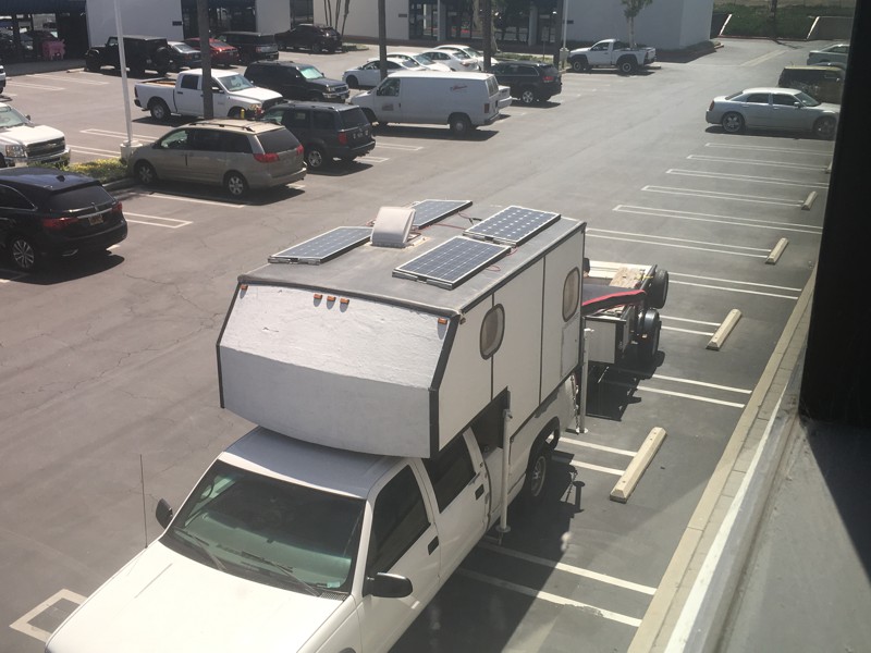
As I said in an earlier post my electrical system runs off my batteries and the solar is one of the methods for recharging them. I went with four 100 watt monocrystalline panels that were built with a glass top and aluminum frame. This should be more than enough to recharge my batteries everyday but only if I get direct sunlight for more than 5 hrs a day. Most of the time having the panels mounted directly to the top of the camper would be plenty but for those times when I don’t get as much sun I decided to make a tilting frame for each panel.
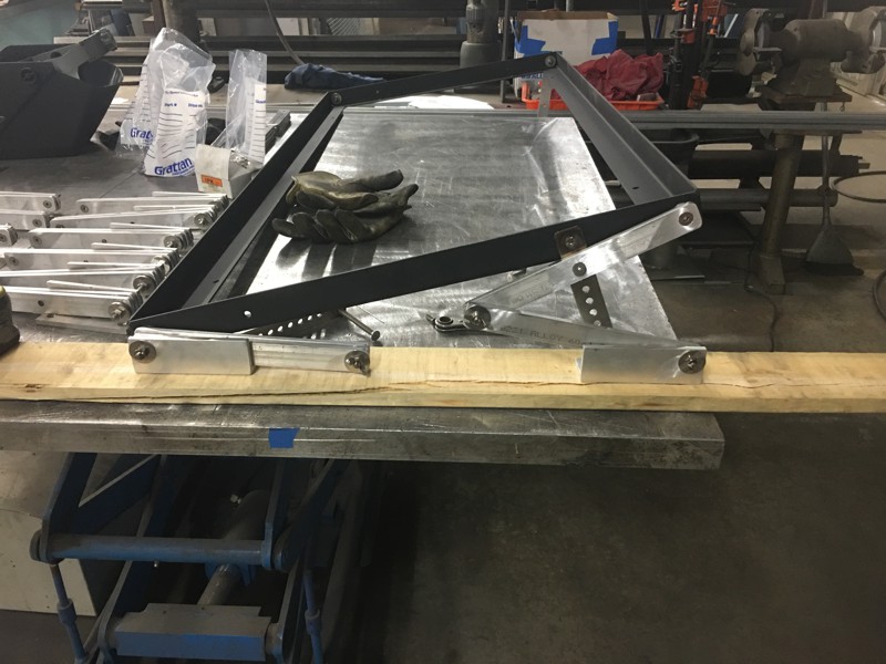
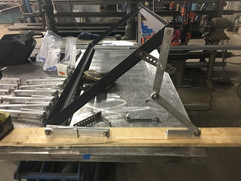
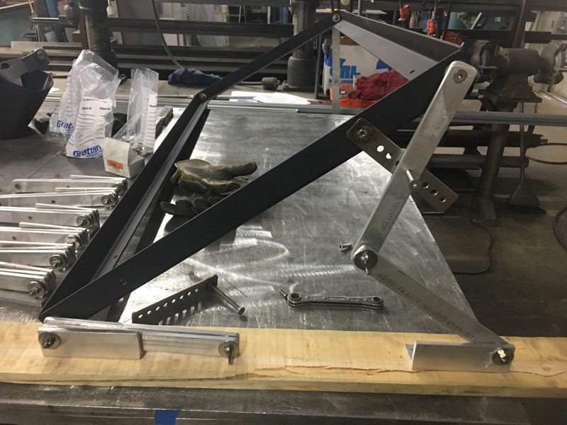
I first built a frame out of bent up sheet metal and made my kicker legs out of aluminum flat bar. To be able to lock it in at different angles I made a stainless steel kick stand with multiple holes. To attach to the camper I used aluminum angle. The flat bar pivots in three places creating a scissor effect and having one on each corner allows me to tilt the panels in all directions so it won’t matter how I park.
I know that this tilting frame is over kill. As I’ve been on the road for two weeks so far I have yet to deploy them. I did this for those times when I’m not getting as good of sun like on days when it’s raining or snowing or for days when I’m up in the far north and the sun isn’t out for as long. I may need to buy a generator at some point but having the tilting panels will delay that a little longer.
Using the inverter as a charge controller does allow me to add more solar panels, up to double what I have, which I may do at some point but if I do I won’t mount them to the top of the camper but instead I’ll make them portable so I can park in the shade and have the panels on and extension cord out in the sun. Someday, maybe.
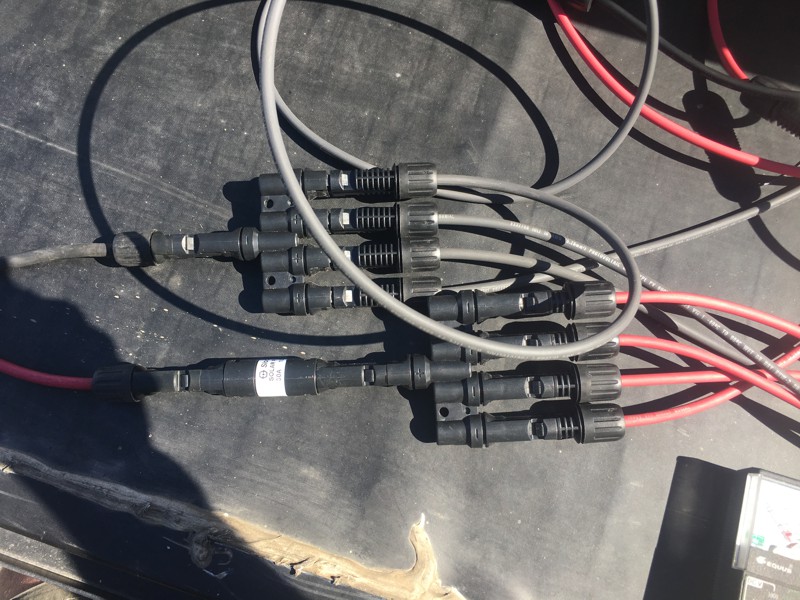
For wire I used 10awg from the panels to the splitter then 8awg from the splitter down into the inverter/charge controller. I used MC4 connectors and wired them in parallel to keep the 12v, series and parallel work the same with solar panels as it does with batteries as described here. I put in a water proof 30amp fuse that plugs into the positive side of the splitter for protection.
This pretty much concludes this series on my electrical. I hope you’ve enjoyed it. If you are thinking about doing this yourself please consult someone that knows how these systems work. I left a lot out and this was truly just for your entertainment. That said, it’s really not that hard to get the right information so don’t let it intimidate you. Just know that making the wrong move could damage your equipment or worse, it could kill you.
0 Comments