
This is part three of my electrical system, for part one go here. In this part I’m going to talk about the lighting and outlets as well as some changes that needed to be made to the main electrical. Once again this is for entertainment purposes only and is not intended to be instructional in anyway. If you attempt any of this and blow your shit up I’m not responsible.
Light and switches:
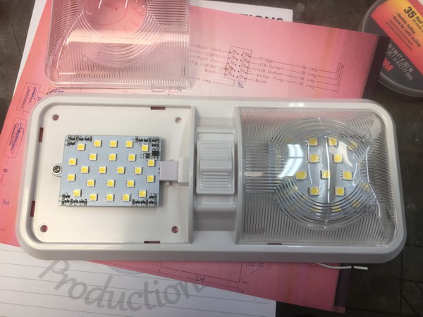
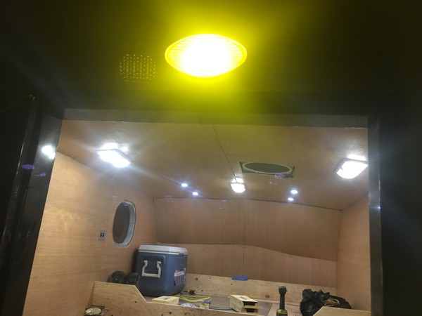
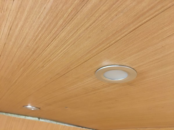
My primary lights are 12v LED RV ceiling dome lights I got off of Amazon. They either put out 275 lumens or 550 lumens depending on if you turn on one side or both but even with both sides on they only draw 6W. They came in packs of 2 so I bought 4 and put one in the sleeping area, two in the main cabin over the benches and table, and one will go over the stove and sink. These are overkill, when I turn on just the two lights in the main cabin it is really bright. I’m not complaining though, I like to be able to see and I can always use the switches on the lights to turn off one side of the light. I may put a dimmer on them eventually.
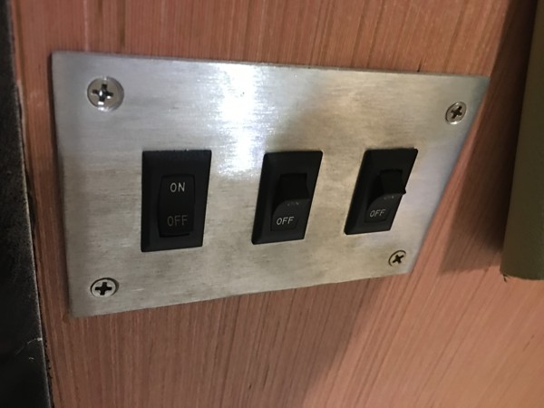
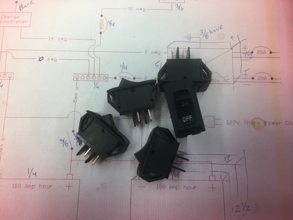
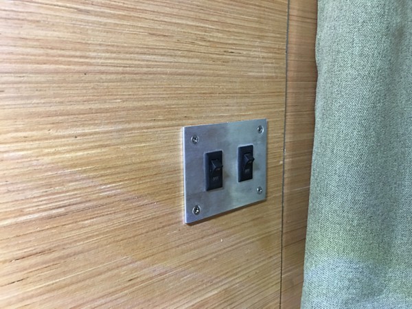
I custom made a switch plate that holds three switches and mounted it near the door. The first switch controls the two main cabin lights with the middle one controlling the exterior door light with and amber lens. The last switch will control the light over the kitchen area once I install it, for now its inactive.
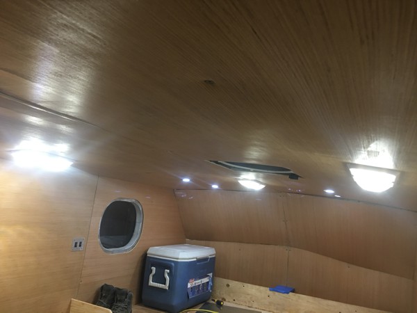
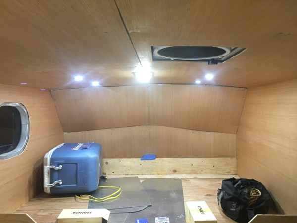
I added 4 additional 12v LED recessed puck lights in the sleeping area with two on each side that will act as reading lights. I put these lights on two separate switches, by the bed, with one switch controlling the lights on the driver side and the other switch the passenger. The main light in the sleeping area doesn’t have an additional switch it turns on and off by the switch that is built into it. I figured it would be easier to reach the light from either side of the bed whether my head was on the driver of passenger side.
Outlets:
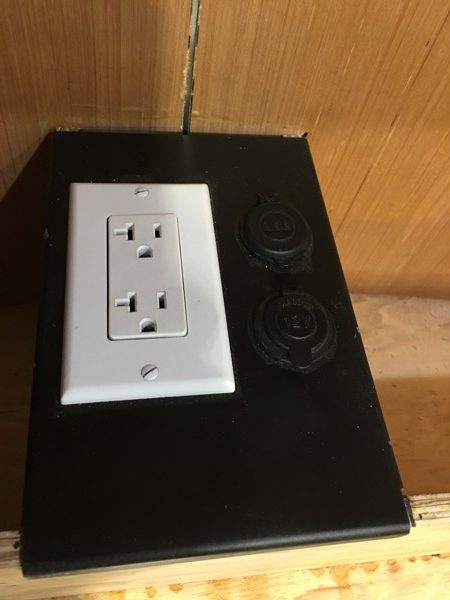
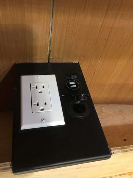
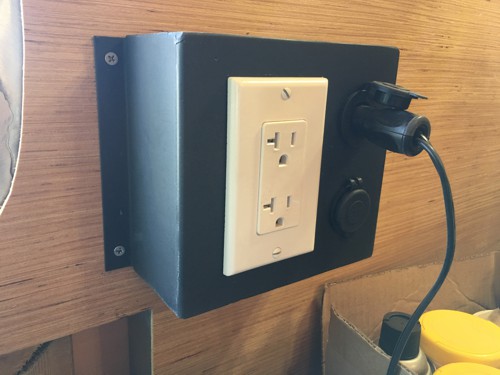
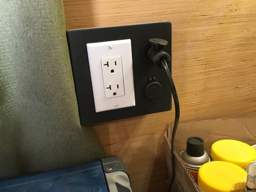
Rather than take DC power invert it to AC then plug in a transformer to convert it back to DC to charge my phone I installed 12v USB outlets as well as a 12v “cigarette lighter” socket next to the 120v AC in the sleeping area. I did the same up near where the sink will be and for now I have my fridge plugged into it. Eventually the fridge will go on the other side of the camper. Both of the boxes are custom made from .090 aluminum.
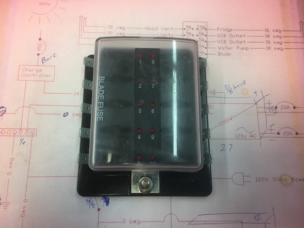
All of my DC power is run through a fuse box that takes regular blade type 12v fuses. I don’t have any of the AC hooked up yet, for now I run my coffee maker off the plug on the back of the inverter. Eventually I will have a 20amp, AC breaker in and will be able to power all of my outlets. For now they are wired with wires running through the walls back to the inverter but not hooked up.
Battery Gauge:
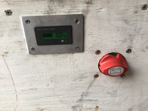
I added in a battery gauge that helps me track the charge of my batteries. This is wired directly to the batteries before going to the buss bar. To check it during the day I do have to isolate the solar panels so I’m not reading the current coming from them but this can be done by turning off the main power switch (shown in picture). At night the solar panels shouldn’t affect the gauge as they wouldn’t be charging the batteries.
Changes to main system wiring:
Just before I left LA I noticed that my charge controller wasn’t working. There are three LED lights that indicate whether or not it’s charging and they weren’t on. Knowing my batteries could run my fridge for 4 days without draining the batteries more than ½ I decided to deal with it when I got to Vegas. Vegas is where my buddy lives that helped me lay all of the electrical out, I’d rather have him there to help me trouble shoot it. I was pretty sure I had just blown the fuse near the solar panels but why not get an expert opinion.
When I got to Vegas we grabbed a multi meter and started testing, it turned out the fuse up top was fine but the breaker between the charge controller and the batteries had broken. It wasn’t tripped but the terminal had come loose and wasn’t making proper contact (cheap amazon breaker). Then my buddy noticed I had the wrong charge controller for my batteries, it was for gel, sealed, or lead acid batteries but not AGM. This meant the charge controller would only charge the batteries up to 70%-80% and that they would never see a full charge.
A little bit of research and we figured out that the inverter I had has a 60amp charge controller built into it and I didn’t even need a separate charge controller. My Buddy’s the one that sold me the inverter but he had forgotten that it had that feature, it was a couple of years ago. We rewired everything eliminating the charge controller and connecting to the back of the inverter making it the charge controller.
Everything is working much better now. The highest charge I got before was 12.9v and now I’m hitting 13.5-13.7 which is the max charge for my batteries. It seems to charge a little faster as well but that could just be a false perception. This does mean one less component to go bad which makes me happy. The charge controller in the inverter is a higher quality than the freeby I got with my solar panel kit meaning cleaner energy going to the battery but it also has twice the capacity so if I decide to add more panels I can, the other controller was maxed out.
0 Comments